Jump to a question in this guide
- Why does the kind of heated floor matter?
- How do the main electric formats compare?
- Loose heating cable: what is the cable doing?
- Cable on mesh: what does the mat change?
- Cable in a shaped membrane: which part heats?
- Foil with heating wire: why does the floating floor matter?
- Electric mats between the joists: how is this different?
- Conductive film: why are the dark strips and edge connections different?
- What happens between switching on and feeling a warm floor?
- What can the sensor and wall display actually tell you?
- Why can warm-up time and everyday comfort change?
- Can floor warming replace the room’s other heat source?
- Why might one area feel different from another?
- Which changes call for stopping use and getting help?
- What do professional electrical and sensor tests answer?
- If a repair is needed, what else may have to be restored?
- What changes when you add a rug or replace the flooring?
- How should you compare a quote and the running-cost question?
- What should you know before calling the job finished?
- Identify the actual heater and its floor construction before comparing controls or repairs.
- Cable, carrier mesh, a shaped membrane, foil-wire and conductive film have different physical jobs and compatibility needs.
- A below-subfloor electric mat is different from a heater beneath a floating finish.
- A sensor describes its local condition; the display is not a map of the whole floor.
- Underfoot comfort, whole-room heating and running cost need different evidence.
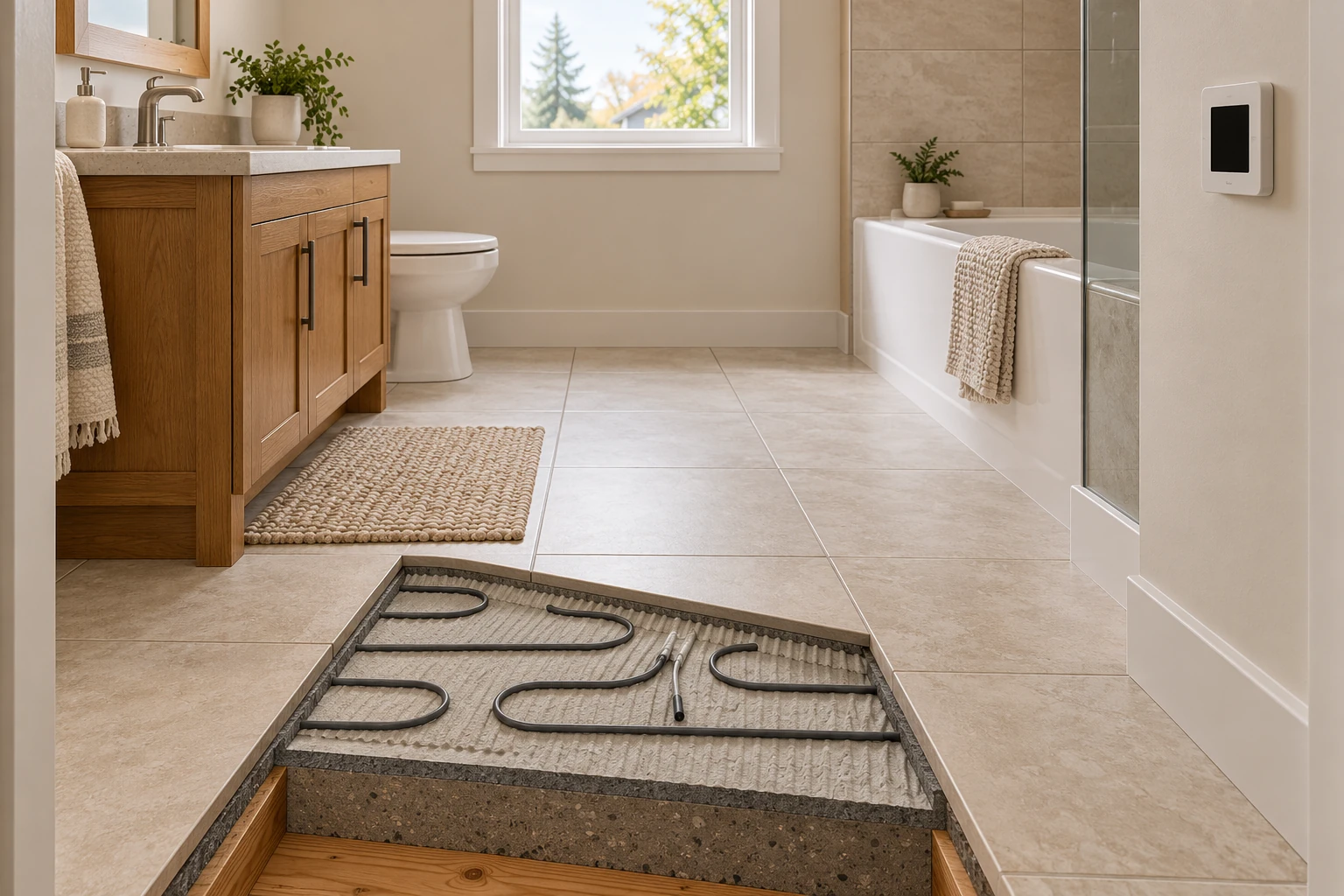
The cable produces heat beneath the tile, while a separate probe senses a local condition. Material is removed to reveal the parts. End connections and the complete cable route are omitted; this conceptual illustration gives no layout, embedding-depth or whole-room capacity specification.
About this illustration
10 picture lessons appear beside the questions in this guide. Use them to understand the explanation, then consider what it means for your home.
Why does the kind of heated floor matter?
You step onto a cool bathroom floor, but the thermostat says it is heating. Or you are changing the flooring and discover that something electrical is hidden underneath. Before deciding the heater is broken—or buying a replacement control—it helps to know what is making the heat and how that heat reaches the surface.
An electric floor has several connected jobs. The heating element turns electrical energy into heat. Materials around it carry and store that heat. A temperature sensor gives the control information from an identified place. The thermostat controls operation according to its actual mode. The sensor is not the heater, and a glowing display is not a picture of everything happening below the floor.
The familiar zigzag cable is only one physical form. There are cables fixed to mesh, cables held by a shaped membrane, wire enclosed in foil, mats suspended below a timber floor and thin conductive-film products beneath suitable floating finishes. Two products sold as a heating mat can need very different floors and controls.
Water-heated floors are another family. A heat source warms circulating fluid, which carries heat through tubing in a floor before returning. That distribution can also serve other emitters. This article explains electric floors; the companion hydronic guide follows the water route and its different floor constructions.
Start with the goal as well as the product. Warming the walking area of a bathroom is different from meeting the whole room’s heating demand on a cold day. A useful explanation tells you which job was designed, rather than promising that every warm floor can replace the rest of the heating.
The room, the hidden heater and the separate sensor
The cable produces heat beneath the tile, while a separate probe senses a local condition. Material is removed to reveal the parts. End connections and the complete cable route are omitted; this conceptual illustration gives no layout, embedding-depth or whole-room capacity specification.
Choose a part name to highlight its explanation below.
- Heating cable
The cable is the hidden heat-producing element in this selected example.
- Separate sensor
The probe senses a local condition rather than making heat.
- Closed wall control
The actual model and operating mode determine control behaviour.
How do the main electric formats compare?
First separate the heater from the material holding it. A loose resistance cable and a cable on mesh can make heat by the same electrical mechanism. The mesh changes its physical arrangement. A shaped membrane can hold a separate cable while performing other specified assembly functions. It is not a different fuel or a sheet that heats by itself.
The location matters just as much. Some electric heaters are embedded above the subfloor; a foil-wire or conductive-film product can sit in a particular floating-floor assembly. The below-floor mat shown later is different again: it works from the joist space beneath the timber subfloor, with its own air-space and insulation requirements.
Use the comparison beside this chapter to find the type you have, then read its individual breakdown. Compare the physical heater, its carrier, the floor combination and where a repair would need access. Do not choose from a universal cheapest-to-best ranking. The actual layout, supply, control, room and finished flooring still have to work together.
These six researched examples cover distinct electric arrangements rather than every product sold in Canada. A product name such as infrared, foil or mat does not settle its construction, local acceptance or suitable finish. Ask for the exact heater and the complete proposed floor assembly, not just an advertising category.
Six electric floor-heating arrangements at a glance
- Loose heating cableManufactured resistance cable in a planned supported and embedded arrangement. The planned coverage can follow usable floor area. The cable is not ordinary wire that can be shortened; its embedding and accessories must suit the system. How are the actual layout, surrounding layers and later access coordinated?
- Cable on open meshHeating cable held on a carrier mesh; the mesh is not the heating element. Part of the cable arrangement is supplied on a carrier. Room geometry, permanent fixtures and suitable embedding still need planning. Which product and floor layers are specified, and how are turns and connections handled by the installer?
- Cable in a shaped membraneSeparate cable retained by a moulded carrier with specified assembly functions. Heater placement and tile underlayment can be coordinated in one named system. Other finishes have different requirements; a membrane alone is not completed waterproofing. Is the proposal a direct-tile or alternate-finish assembly, and which other functions are included?
- Wire enclosed in foil above the subfloorHeating wire enclosed in reinforced foil below a qualified floating-floor finish. A particular dry floating-floor construction can avoid a tile-mortar arrangement. The exact covering, underlay and control matter; it is not a universal tile, wood or carpet product. Does the current complete product guidance agree with the proposed floor combination?
- Wire-and-foil mat in the joist spaceAn identified electric mat below a wood subfloor, with its designed airspace and insulation relationship. A suitable accessible-below project may avoid removing the finish above. Joist access, obstructions, heat leakage and the existing floor limit the proposal. How will this particular below-subfloor arrangement deliver heat through the existing construction?
- Conductive filmA manufactured film mat with heating strips and conductive edge paths beneath a compatible floating finish. A distinct thin-format option for an appropriate floating-floor project. Product-specific substrate, covering, sensor-margin and use restrictions remain. Which exact model, covering and sensor arrangement are proposed, and is local approval established?
These researched examples explain different constructions. Confirm the exact product, complete assembly and local requirements for the actual home.
Further reading: NUHEAT · Cable Installation Guide, 2504 / April 2025; Warmup · StickyMat instructions, v1.0 January 2015; Schluter Systems · DITRA-HEAT Installation Handbook, 10/2025; Warmup · Foil Installation Manual, V4.0 2013; SunTouch · UnderFloor Mat Series U10 Installation Manual, 2022; MP Global Products · QuietWarmth Float Installation Instructions.
Loose heating cable: what is the cable doing?
A loose-cable system uses a manufactured heating cable laid out in a planned pattern. In the illustrated embedded example, supporting accessories hold the cable while the specified material surrounds it. The thin cable makes heat; the surrounding material transfers that heat toward the floor finish and also into connected material below.
This format lets a designer arrange coverage around the actual usable floor area. That can be useful in a room whose shape does not suit one simple rectangle. It does not make the cable an ordinary piece of wire that can be shortened to fit. The cable and its permitted supporting arrangement remain an identified system.
The practical tradeoff is the amount of coordination hidden by the finished floor. The layout, connections, sensor, embedding material and finish all need to suit the system. NUHEAT’s April 2025 guide, for example, identifies its approved cable-support accessories and requires its heating portion to be embedded. That is a named example, not permission to combine any cable and membrane.
Damage before or after concealment is an important service question. Later drilling, aggressive grout work or other sharp-tool work can affect a concealed cable. An uneven floor sensation alone cannot tell you whether that happened. Give the provider the history of the change and any available layout photographs rather than cutting a tile to search for a fault.
The useful question for a quote is: “Where is this heater intended to go, what surrounds it, and how will the completed work be checked?” For an existing floor, ask whether the original layout and installation-stage results are available. They help identify the system without turning an old record into a guarantee of its present condition.
Cable and mesh: find the actual heating element
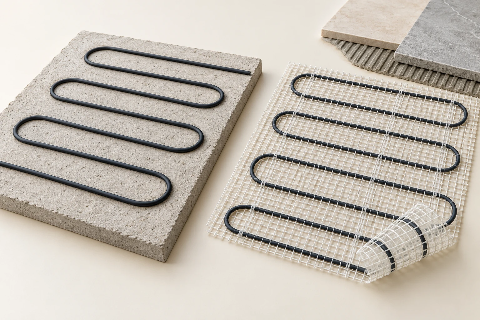
The cable makes heat in both examples; the mesh holds an arrangement. The cutaway is conceptual, with connections and the complete embedding assembly omitted.
Choose a part name to highlight its explanation below.
- Heating cable
The manufactured cable is the heater.
- Mesh carrier
The open mesh holds cable in a planned arrangement.
Cable on mesh: what does the mat change?
A mesh-mounted mat makes the heater easier to recognize. You can see a heating cable attached to an open carrier. In the Warmup example, the carrier is fibreglass mesh; it is not a metal mesh that produces the heat. The cable is the resistance heater, while the mesh holds its arrangement during the specified floor work.
A prearranged mat can simplify planning across an area that suits its form. Rooms still have edges, fixtures and changes of direction, so a supplied mat is not a finished design for every floor. The actual heated area must be planned separately from the room’s full dimensions.
The carrier and the heater must not be confused during work. The named manual distinguishes adapting the carrier from damaging the heating cable. That is a reason to use the actual instructions and qualified installers, not a cutting lesson for an owner. This guide gives no mat-cutting, cable-spacing or connection procedure.
The floor materials above and around the mat matter. A tile finish relies on its own support and bonding assembly, while the electrical heater needs the specified embedding and protection. A picture of neatly rolled mesh does not tell you whether the completed tile base or the concealed cable is sound.
Ask how the installer will coordinate the mat, sensor, joints, finished floor and later fixture fastening. Keep the actual location and stage with installation photographs. If the floor changes after work nearby, report that sequence; do not assume that replacing the thermostat will correct a damaged heater or an unrelated tile problem.
Cable in a shaped membrane: which part heats?
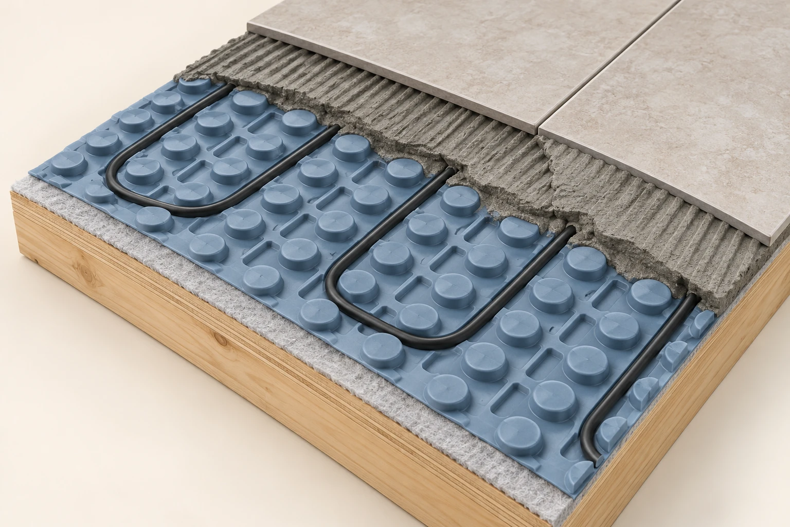
Here the separate cable sits in the spaces of a moulded carrier. In the named Schluter example, the membrane has a fleece backing and raised shapes that retain the cable. Mortar and the finish form other parts of the assembly. The cable makes heat; the membrane is not itself the electric heating element.
The attraction is an integrated floor arrangement with identified functions, rather than adding an unidentified cable to an unrelated layer. In its specified applications, this carrier also has an uncoupling role: it helps manage movement between the substrate and tile assembly. That is different from promising that every crack in every floor will be prevented.
The cutaway shows one direct-tile example. It should not be copied unchanged for wood or resilient finishes. The October 2025 handbook has different requirements for those coverings, including a specified encapsulating layer. Choosing a finish changes the assembly question, even where the same family name appears on the membrane.
Waterproofing needs its own explanation too. The presence of a membrane under a bathroom floor does not establish that all seams, edges and transitions form a completed waterproof assembly. Ask which function is included in the actual scope and how its details will be completed. Floor heat and water management are connected construction work, not interchangeable claims.
For service or renovation, identify the cable and membrane together with the finish and supporting base. Product compatibility, a concealed electrical concern and a cracked tile can require different assessments. The useful proposal explains which of those questions it addresses instead of treating an attractive membrane photograph as the whole answer.
A shaped membrane holds a separate cable
The separate cable makes heat; the shaped membrane is a carrier with specified assembly functions. This illustration does not establish waterproofing or approval for another finish.
Choose a part name to highlight its explanation below.
- Cable
The separate cable produces heat.
- Shaped carrier
The studs hold the cable arrangement.
- Tile and mortar
The selected cutaway illustrates the covering above.
Foil with heating wire: why does the floating floor matter?
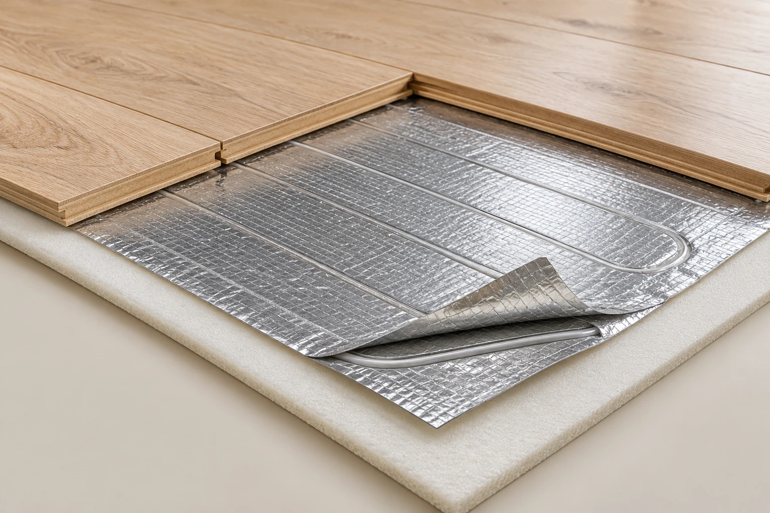
A foil-wire heater is not a roll of reflective insulation. In the Warmup example, insulated heating cable is enclosed between reinforced aluminium-foil layers. The wire produces heat and the foil helps distribute it across that product. Its electrical and protective construction is manufactured as a system, not improvised from a sheet of foil.
The pictured example places the product over a compatible underlay and below an approved floating laminate or engineered-wood floor. A floating finish is laid as its intended floor system rather than fastened through the heater. This illustrates one qualified dry construction; it is not a tile-and-mortar system.
That arrangement can be relevant when a suitable floating finish is already part of the project. Its constraint is the whole combination: substrate, underlay, heater, covering and control. A package saying suitable for heated floors does not establish that a particular thick board, attached pad, adhesive or rug suits this particular heater.
Folds, punctures, sharp edges and furniture or coverings that trap heat are concerns identified in the named instructions. Do not use screws, nails or other floor fastening to discover where the product lies. Tell the flooring contractor that heat is present before the finish is removed or replaced.
The manufacturer’s currently linked PDF is an older 2013 edition and differs from current web wording on a floor-thickness detail. No thickness or temperature from it is offered here as a general Canadian rule. Have the supplier and qualified provider resolve the current instructions for the exact proposed product. Carpet is a separate qualified construction question, not an automatic extension of this floating-wood picture.
Wire enclosed in foil below a floating floor
The heating wire is enclosed in reinforced foil above a protective underlay. This selected floating-floor example does not establish suitability for every wood, tile or carpet product.
Choose a part name to highlight its explanation below.
- Enclosed wire
The wire makes heat within the reinforced foil.
- Underlay
The protective layer belongs to the selected assembly.
- Floating finish
The covering must suit the exact product.
Electric mats between the joists: how is this different?
Some electric floor-warming products work from below the timber subfloor. SunTouch UnderFloor is one example: a heating wire and foil radiator form a mat installed in the joist space. It is a different product from the foil-wire mat placed immediately beneath a floating finish.
The air space above the named UnderFloor mat is intentional. Heat from the mat reaches the underside of the wood floor across that space, and then moves through the floor construction. Insulation below and the treatment of the heated joist space are part of its specified arrangement. This should not be redrawn as a hydronic metal plate pressed against the subfloor.
Its practical attraction is access from below: a suitable project may be able to address floor warming without removing the finished surface above. That depends on accessible joist spaces and an appropriate floor, not simply on there being a basement. Pipework, ducts, blocking and the condition of the existing construction are matters for the installer’s assessment.
The tradeoff is that the heat must pass through the existing subfloor and finish. The manual expressly relates performance to floor materials, insulation, starting conditions and heat escaping from the joist space. A thick covering or an incompletely addressed space can change the result. No guaranteed floor-temperature rise is adopted from the manual.
Sensor arrangements also differ. The named manual discusses sensing associated with the subfloor or finished-floor area and explains that a reading from below is not automatically the exposed floor-surface temperature. An owner should not copy a probe position from a tile-cable picture or drill into the floor to add one.
Ask the provider to show the intended heat path, identify the controlling sensor and explain which construction is included in the work. Keep the model and photographs with the handover. If warmth is disappointing, the mat, control, joist-space treatment and covering deserve a connected assessment—not an assumption that a higher thermostat target fixes them all.
An electric mat below the wood floor
This electric wire-and-foil mat works from the joist space. The illustrated airspace and insulation relationship differs from a water tube in a contact plate; dimensions and connections are omitted.
Choose a part name to highlight its explanation below.
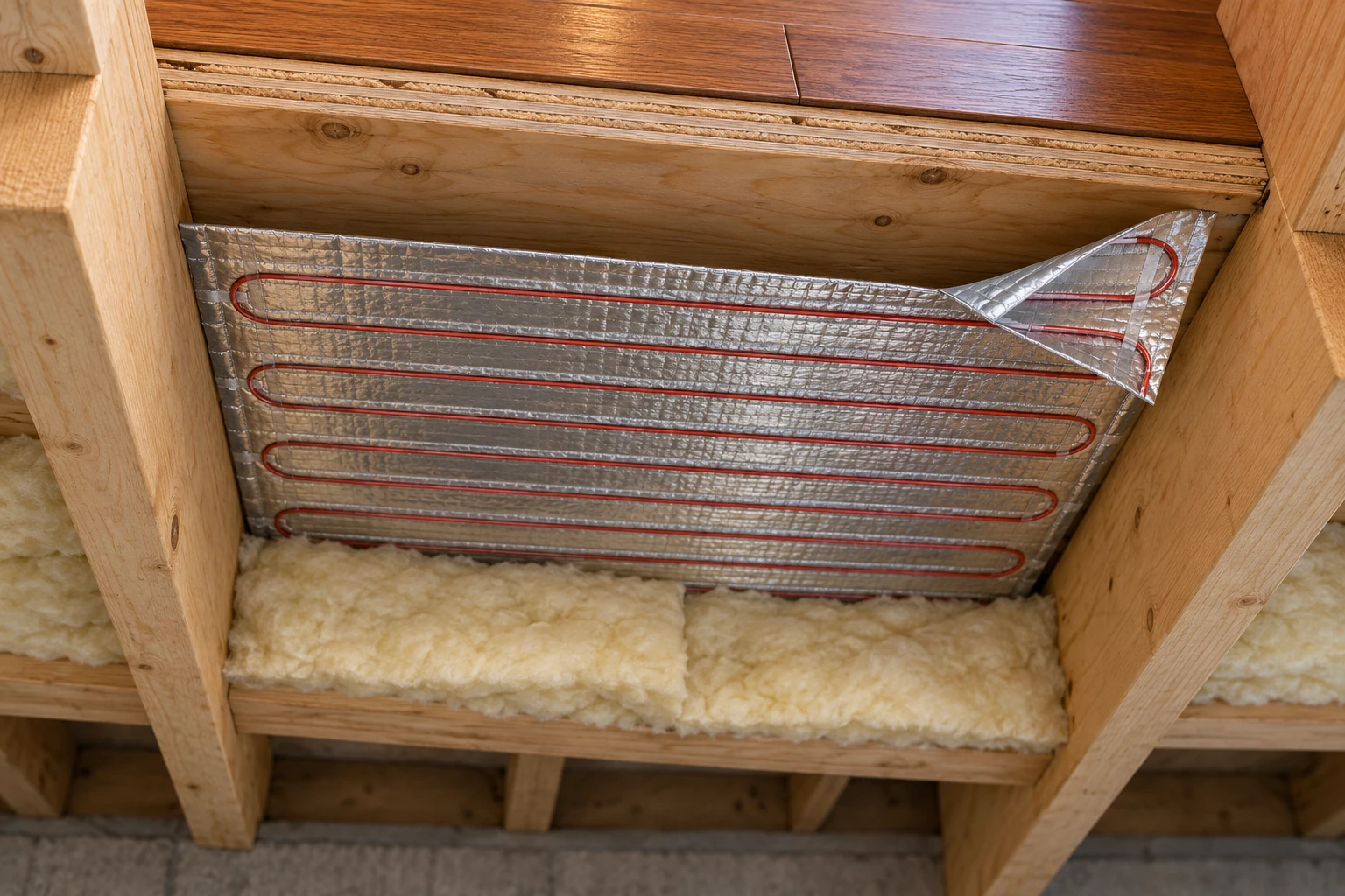
- Wire and foil
The resistance wire and metallic radiator form the illustrated heater.
- Airspace
The selected system leaves an airspace above the mat.
- Insulation below
The illustrated lower insulation limits heat escaping downward.
Conductive film: why are the dark strips and edge connections different?
A conductive-film heater is another physical arrangement. The QuietWarmth Float example has dark heating strips and conductive edge busbars within a thin manufactured mat. It is not the same object as a round cable wound across mesh, or heating wire enclosed in an aluminium-foil radiator.
Electrical current reaches the heating portions through the product’s designed conductive paths. Heat then passes through the compatible floor above. The picture makes those broad parts recognizable; it is not a wiring diagram or an instruction to expose or connect the mat.
This example belongs beneath specifically compatible floating flooring. Its thin form may suit a planned floating-floor project, but it does not remove the need for a sound prepared substrate, suitable covering and matched controls. The manufacturer’s finish and substrate conditions belong to this product, not to all products described as film.
The mat is vulnerable while exposed and can be damaged by protrusions, punctures, creasing or inappropriate work. Coverings and low furniture can also trap heat where the product’s instructions prohibit them. A change to the floor or room furnishings is therefore a system question, not only a decorative choice.
Its sensor detail is a useful example of why generic instructions fail. The retained manual locates its sensor beside the long edge in the clear margin, away from the heating strips and busbar; it is not a probe placed on top of or beneath the film. A between-cable detail from another product is not transferable. The qualified installer follows the exact complete instructions; the reader only needs to understand the different relationship.
Do not infer permission to trim, join or modify one heater from what another mat’s manual allows. Film and cable products can have different manufactured boundaries and permitted work. This article gives no cutting procedure. Canadian use also requires the actual model’s applicable approval and local review; a Canadian paragraph in a downloaded manual is not independent verification of a current product listing.
Conductive strips are different from foil-enclosed wire
The dark strips and conductive edge path belong to a researched film format. The probe is beside its clear edge margin; sensor placement and suitable flooring remain exact-product questions.
Choose a part name to highlight its explanation below.
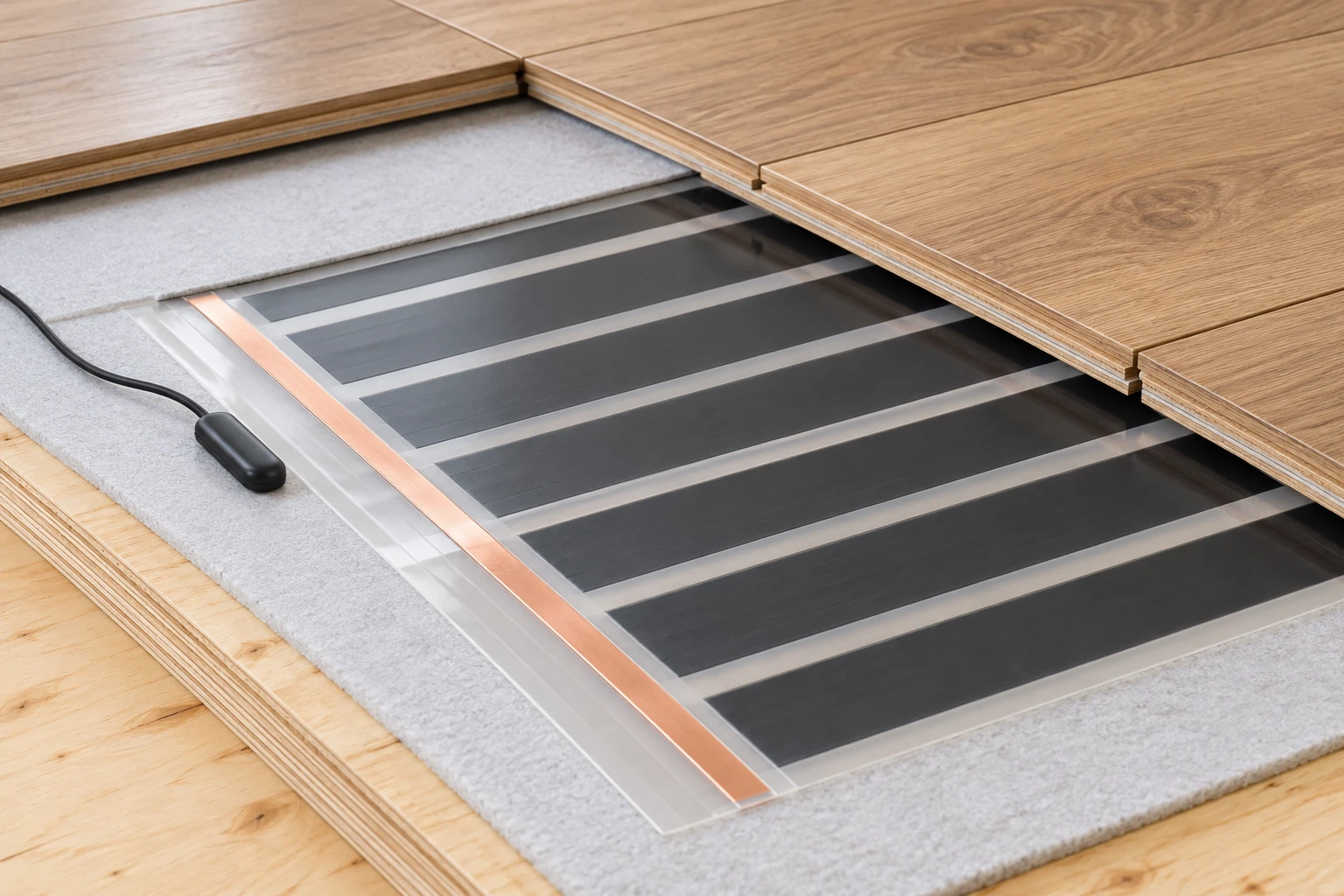
- Heating strips
The dark conductive strips produce heat.
- Edge path
The side conductor is part of this film format.
- Separate probe
The pictured sensor sits beside the clear margin, away from the heating strips.
What happens between switching on and feeling a warm floor?
Electrical resistance produces heat in the heating element. From there, the assembly determines where that heat goes. Touching materials pass energy by conduction. The warmer finished surface can exchange radiant heat with cooler surroundings and transfer heat to nearby air. Your foot also exchanges heat through contact with the surface.
The layers are not invisible packaging around an instant heater. They have their own temperature and capacity to store heat. An embedded cable warming a substantial base is doing a different physical job from a thin heater immediately below a particular floating finish. That is why a product-only comparison cannot promise the same response in every room.
Heat can also travel toward the base and other connected material. A layer intended to limit that path is not automatically a complete insulation design. Ask how the actual supporting floor, insulation and intended finish were considered, particularly above a colder space or a concrete base.
Once electrical input stops, the floor does not instantly lose stored heat. Continued warmth after a control stops calling can fit that mechanism. It does not, by itself, prove that the control is stuck on; nor does it excuse abnormal heat or another unsafe condition. The actual system and concern still determine the response.
Use the cutaways to compare routes, not to copy a stack of products. Floor support, movement, moisture management, electrical safety and heating performance are separate jobs that the completed assembly must coordinate. A layer that solves one of them does not automatically solve the others.
Explore the eight-stage cable and floor lesson
Follow electric floor warming through control, cable and floor
Choose any stage or play the lesson. A complete pass from stage 1 lasts 64 seconds, with eight seconds per reading stage during playback. Paused and manually selected stages remain available as long as you need. These highlights are not physical cycle times, control settings, measured performance or a test result.
The named North American DITRA-HEAT example uses the retained 10/2025 handbook and Canadian DITRA-HEAT-E-R product page. Other assemblies and controls differ. No electrical connections, settings or response times are supplied.
- Thermostat: Controls the matched heating cable using the relevant temperature information.
- Floor sensor: Reports temperature at its location; it is not the heating cable.
- Heating cable: Converts electrical energy into heat within the assembly.
- Floor and substrate: Receive and transfer heat; their construction affects the response.
- Protection and records: Matched protection and qualified installation records are separate from a warm surface.
Paused at stage 1 of 8.
Keyboard: use Tab to reach a control and Enter or Space to activate it. On a stage button, Left/Right selects the previous/next stage; Home/End selects the first/last stage.
Identify the matched control and floor
Start with the installed thermostat, cable and floor assembly. In this named example the DITRA-HEAT-E-R thermostat controls matched heating cables and includes a floor sensor. A similar-looking thermostat does not identify the concealed cable or substrate.
Useful question: Which model labels and assembly records belong together?
All eight reading stages
Identify the matched control and floor
Start with the installed thermostat, cable and floor assembly. In this named example the DITRA-HEAT-E-R thermostat controls matched heating cables and includes a floor sensor. A similar-looking thermostat does not identify the concealed cable or substrate.
Useful question: Which model labels and assembly records belong together?
The floor sensor reports local temperature
The sensor responds to temperature at its position in the floor assembly. It provides information to the thermostat; it does not generate the floor heat. Its location and covering conditions matter to what it reports.
Useful question: What records identify the sensor and its intended location?
The thermostat controls electrical heating
The matched thermostat controls the heating cable according to the actual system and its settings. The dashed information route and solid energy route have different jobs. This diagram is not a wiring diagram or an instruction to alter a setting.
Useful question: Which operating instructions and control mode apply to this model?
The cable converts electricity into heat
Electrical resistance in the heating cable produces heat in the floor assembly. This is different from a heat pump moving heat from another source. The drawing shows the cable conceptually, with no usable spacing or connection detail.
Useful question: What establishes the installed cable identity and qualified installation?
Heat moves through the floor assembly
The cable warms the surrounding assembly and floor covering. Heat also moves toward the substrate. Concrete, insulation, starting conditions and the actual construction can change the response; the lesson clock predicts none of them.
Useful question: What floor and substrate construction is documented?
A warmer floor affects the occupied space
The warmer surface transfers heat to its surroundings and can improve underfoot comfort. Floor warming does not by itself establish enough heat for the whole room. The manufacturer calls for a professional assessment of the space-heating need.
Useful question: Was floor comfort or whole-room heating the actual design purpose?
Control information and protection remain separate
The sensor provides feedback while the matched control regulates heating. The named thermostat also has built-in ground-fault protection, but a protection device is not a diagnosis or proof of every concealed condition. Do not reset a fault or expose wiring to follow this lesson.
Useful question: What exact warning, protection and qualified service instructions apply?
Retain the installation and service evidence
Keep model information, installer test records, assembly details and the applicable manuals. A warm patch or a display value cannot establish cable integrity, full-floor response, whole-room capacity or warranty coverage. Record concerns for the qualified provider rather than reproducing a fault.
Useful question: Which record or professional assessment is still missing?
Use the source notes in this guide to check the named examples, adopted scope and limits.
What can the sensor and wall display actually tell you?
A sensor responds to conditions at its own sensing element. The thermostat interprets that signal according to its actual operating mode and configuration. A displayed target is not necessarily the measured floor temperature, and a floor reading does not describe every part of the room.
Some illustrated cable systems put a sensor between particular heating runs. The film example instead uses its specified clear-edge arrangement, and the below-subfloor example has its own subfloor-related options. These differences explain why sensor location and controller compatibility belong in the actual design. There is no universal probe position in this guide.
A closed control may show that it has power, a selected mode or a heat request. Those are useful observations, but they do not separately measure supply to the heater, its electrical condition or heat delivered across the whole floor. Record the actual words or icon and use the matching manual rather than naming a fault from an unfamiliar display.
The sensor and controller need to suit one another as well as the heater. A replacement with a similar faceplate is not proof of a compatible pairing. Ask the qualified provider which existing components can remain, how the match is established and what assessment follows the change.
Use only the intact control’s ordinary user functions as its instructions allow. Do not remove its faceplate, disconnect sensing leads, bridge protection or apply a meter to investigate. A suspected sensing problem is a professional service question, not a reason to try several unrelated replacement thermostats.
Two routes: heat and sensing
The sensor reports a local condition to the controller; the heater’s operation is a different route. This cable example does not supply a film or below-subfloor sensor detail.
Choose a part name to highlight its explanation below.
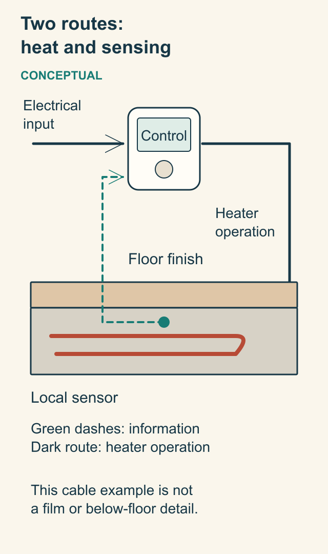
- Heater
The manufactured element makes heat when its actual supply and control permit operation.
- Sensor
The probe reports conditions at its identified sensing location.
- Controller
The model and operating mode determine how the signal is interpreted.
- Different products
A cable-run sensing illustration is not a universal location rule for film or below-subfloor systems. No wiring or installation detail is supplied.
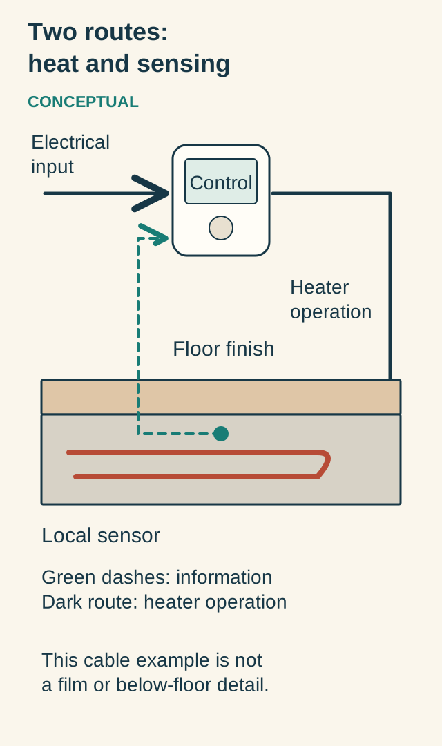
Two routes: heat and sensing
The sensor reports a local condition to the controller; the heater’s operation is a different route. This cable example does not supply a film or below-subfloor sensor detail.
- Heater
- The manufactured element makes heat when its actual supply and control permit operation.
- Sensor
- The probe reports conditions at its identified sensing location.
- Controller
- The model and operating mode determine how the signal is interpreted.
- Different products
- A cable-run sensing illustration is not a universal location rule for film or below-subfloor systems. No wiring or installation detail is supplied.
Read all the diagram text
- Two routes: heat and sensing
- CONCEPTUAL
- Control
- Electrical input
- Heater operation
- Floor finish
- Local sensor
- Green dashes: information Dark route: heater operation
- This cable example is not a film or below-floor detail.
Why can warm-up time and everyday comfort change?
A floor starting cold after an absence is not in the same condition as one maintaining ordinary warmth. The heater, connected materials, room losses and the household’s schedule all contribute to the response. Elapsed time without those conditions is not a useful universal performance test.
A schedule describes when the control is intended to seek a condition. The selected target describes that intended condition. Actual heater operation depends on the control and sensing arrangement. A schedule being enabled for several hours does not prove continuous electrical input throughout that period.
Choosing a much higher target does not establish more heating capacity or make every floor reach its goal sooner. QuietWarmth’s operating discussion makes this distinction explicitly; the wider lesson is to understand the installed control instead of repeatedly selecting the maximum. Follow the actual product’s ordinary operating instructions.
Notice whether the behaviour is new. The morning floor after a long holiday, a floor beneath a newly added covering and a floor that suddenly changed after renovation pose different questions. Write down what changed in normal use without deliberately chilling the room, covering a heated area or provoking a fault.
A useful explanation from the provider connects the reported response to the actual heater, base, finish and goal. It might identify an expected response, an unsuitable operating arrangement or a supported fault requiring work. The answer should be specific; “all heated floors take this long” is not a substitute for identifying this one.
Can floor warming replace the room’s other heat source?
Comfort under your feet and heating the whole room are different design goals. A heated walking area can feel pleasant while the room still needs another source of heat. The amount of heat the room loses, the area actually available for heating and the permitted floor conditions have to be considered together.
Available heated area is not necessarily the whole room. Fixed fixtures, unsuitable locations and the product’s intended layout limit the usable footprint. A room-area calculation that silently includes a bath, fitted cabinet or another excluded area can therefore ask the wrong question before any heater is selected.
Some manufacturer documents discuss a primary-heating application when the appropriate heat-loss assessment supports it. Others describe floor warming as their main purpose. Neither statement establishes that your existing installation was designed to replace a radiator, baseboard or ducted system.
If you plan to remove another heater, enclose a different space or change the room’s use, bring that goal to a suitable heating designer and the qualified electrical provider before work is priced. The floor installer, electrical provider and room-heating design may have complementary responsibilities.
No picture here provides a room output, a national design temperature or a promised bill. It should help you ask: “Was this selected to warm the floor, contribute to the room’s heat, or meet the full design requirement—and where is that assessment?”
Why might one area feel different from another?
Start by locating the experience in the room. Is the whole floor different, one walking area, the edge near a window, or a place affected by recent work? A sensation underfoot is useful to describe, but it is not a calibrated map of the heating element or a diagnosis of a broken cable.
The actual layout can leave areas without heating, while materials and conditions change how heat reaches the surface. A covering change, new floor-level furniture or a difference in the base can matter. That is why the provider needs the installed arrangement and the history, not only a close-up of one tile.
A sudden change after floor work deserves a clear account of what was done and where. A failed control, damaged heater, sensing issue and floor-assembly concern are different possibilities requiring their own evidence. Do not select the most convenient explanation solely because the thermostat is easier to reach than the concealed heater.
Keep observations within ordinary safe access: room, date, existing mode or schedule, exact display text and relevant changes. A service provider can choose suitable measurements or specialist methods. Do not drill, lift a board, cut grout, attach improvised instruments or force a high-temperature run to improve the evidence.
If an intermittent concern does not appear at the appointment, retain both the original account and what was assessed at the visit. A useful follow-up says which question remains and what the provider recommends next. A brief normal operation is not a full clearance of every concealed part.
What changed? Ask a better first question.
A cool floor, a changed area, a covering change and recent work lead to different questions. These sketches locate observations; they do not diagnose a concealed heater.
Choose a part name to highlight its explanation below.
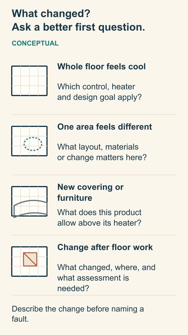
- Whole floor
Identify the actual mode, heater and intended heating goal before choosing a cause.
- One area
Locate the feeling in the room and consider the documented layout, material and history.
- Covering or furniture
Check the actual product’s requirements; some arrangements restrict heat-trapping objects.
- Work nearby
Tell the qualified provider what was done and where. No destructive investigation or forced-heating experiment is shown.
What changed? Ask a better first question.
A cool floor, a changed area, a covering change and recent work lead to different questions. These sketches locate observations; they do not diagnose a concealed heater.
- Whole floor
- Identify the actual mode, heater and intended heating goal before choosing a cause.
- One area
- Locate the feeling in the room and consider the documented layout, material and history.
- Covering or furniture
- Check the actual product’s requirements; some arrangements restrict heat-trapping objects.
- Work nearby
- Tell the qualified provider what was done and where. No destructive investigation or forced-heating experiment is shown.
Read all the diagram text
- What changed? Ask a better first question.
- CONCEPTUAL
- Whole floor feels cool
- Which control, heater and design goal apply?
- One area feels different
- What layout, materials or change matters here?
- New covering or furniture
- What does this product allow above its heater?
- Change after floor work
- What changed, where, and what assessment is needed?
- Describe the change before naming a fault.
Which changes call for stopping use and getting help?
Abnormal heat, a burning smell, visible electrical damage or moisture affecting electrical equipment is a safety concern, not a warm-up experiment. Stop ordinary use, keep clear of the affected equipment and obtain appropriate qualified or emergency assistance. Do not touch wet electrical parts or approach a hazard to operate a control.
Protection that operates needs its model-specific response. Do not repeatedly reset or bypass it to keep the floor warm. The heater, control, sensing and protection must be considered as the actual installed arrangement. An older manual’s wording about one product is not a rule for every present Canadian installation.
During renovation, exposed damage or a suspected puncture is a reason for the responsible qualified provider to assess the system before it is used or concealed again. Do not repair a heating element with ordinary wire, improvised tape or an unrelated kit. The appropriate manufacturer-supported method and restoration scope are part of the professional work.
Less urgent discomfort still deserves a proper question, but not every cool floor is an electrical emergency. If the intact control is operating ordinarily and no unsafe condition is evident, describe the comfort change and arrange appropriately scoped service. The difference is the actual condition, not how reassuring a display looks.
What do professional electrical and sensor tests answer?
An electrical record should identify what was tested and why. The heater’s intended current path, unwanted electrical paths and the temperature sensor are different components or questions. A provider should explain which assessment was performed and what its result supports.
A cable-path assessment does not establish the tile bond, moisture-management details or room-heating capacity. A sensor finding does not by itself demonstrate the condition of every heating portion. Those distinctions help explain why an invoice that only says tested may leave the original comfort complaint unanswered.
Installation-stage records can help show the condition assessed before the heater was concealed and after particular work. Keep their original dates, system identity, responsible person and interpreted results. Do not replace missing measured results with catalogue values or describe an old test as a present inspection.
Different heater technologies can require different methods and limits. A procedure or instrument setting copied from a cable manual may be unsuitable for another product. This article gives no meter range, test voltage, terminal instruction, resistance threshold or permission to perform electrical tests yourself.
The static comparison beside this chapter keeps result fields blank on purpose. Its job is to show what a useful professional record names, not to supply fictional passed readings. Ask the provider to connect the result to the question and identify any further electrical, control or floor-assembly work needed.
If a repair is needed, what else may have to be restored?
Replacing a wall control, addressing a sensor and repairing a concealed heating element are different jobs. Before agreeing to work, ask what finding supports the proposal. A replacement should respond to an identified concern and be compatible with the parts that remain.
Access can be a major part of the scope. An embedded heater may involve work through a floor finish and its supporting layers. A heater below a timber subfloor has a different access question. Neither picture makes the concealed location or repair method known for your home.
Electrical work and floor restoration need to be coordinated. If tile, a membrane, an underlay or part of a floating floor is disturbed, ask who is responsible for restoring each affected function. Repairing a conductor is not the same as completing a suitable finished floor or any water-management detail.
Ask what assessment follows the actual work and what ordinary operation will be explained at handover. Keep the completed scope, new component identities and any remaining question together. A control lighting up answers less than a clear account of the original complaint and the work carried out.
What changes when you add a rug or replace the flooring?
Heat has to leave the floor through the materials above the heater. A new underlay, finish, rug or low solid-base furnishing can change that route. Some named products specifically restrict coverings or objects that trap heat. Do not assume a familiar household item is suitable above every heated floor.
A flooring label saying compatible with radiant heat is a starting point, not approval of the entire combination. The heater’s instructions, the covering’s requirements, the substrate and the intended control all matter. A finish that suits one dry film example may not suit the foil-wire example beside it.
Tell contractors that heating is present before removal, fastening or a change of finish is scoped. Give them the exact heater identity and available layout. Hidden heating can be affected even where the visible work looks like a small trim, fixture or surface change.
Do not drill a test hole or remove the finish yourself to identify the heater. A qualified provider should plan suitable investigation and explain how the electrical system and affected floor layers will be protected or assessed. Missing records make that planning more important; they do not justify guessing a layout.
After completed changes, keep the new materials and applicable operating instructions alongside the original history. The next household should be able to distinguish the original heater from a later controller or covering, rather than assuming the newest invoice describes the whole system.
A warm floor is part of a room heat balance.
The heater supplies heat through the actual floor layers while the room also loses heat. Underfoot comfort is a different design goal from meeting the room’s entire heating requirement.
Choose a part name to highlight its explanation below.
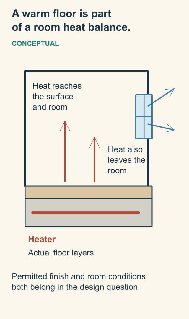
- Heater and floor
The element adds heat; surrounding material carries and stores it before the surface responds.
- Finish
The permitted finish, underlay and furnishings affect the heat route and remain product-specific.
- Room
Available heated area and the room’s heat loss need an actual design assessment.
- Scope
This is not a layout, output calculation or permission to remove another heat source.
A warm floor is part of a room heat balance.
The heater supplies heat through the actual floor layers while the room also loses heat. Underfoot comfort is a different design goal from meeting the room’s entire heating requirement.
- Heater and floor
- The element adds heat; surrounding material carries and stores it before the surface responds.
- Finish
- The permitted finish, underlay and furnishings affect the heat route and remain product-specific.
- Room
- Available heated area and the room’s heat loss need an actual design assessment.
- Scope
- This is not a layout, output calculation or permission to remove another heat source.
Read all the diagram text
- A warm floor is part of a room heat balance.
- CONCEPTUAL
- Heat reaches the surface and room
- Heat also leaves the room
- Heater
- Actual floor layers
- Permitted finish and room conditions both belong in the design question.
How should you compare a quote and the running-cost question?
A useful quote describes the floor you will actually have. It names the heater and format, usable heated area, supporting and covering materials, control and sensor, electrical scope, access or restoration work and the intended heating goal. The comparison is between complete scopes, not simply rolls of cable or the appearance of two thermostats.
Each format has a practical attraction and a corresponding constraint. Loose cable offers a planned arrangement around the room; a carrier mat prearranges part of that layout; a shaped membrane integrates specified assembly functions. Dry foil or film products depend on their approved floor combinations. Below-subfloor mats depend on suitable access and the existing floor route. None wins every project.
All the electric examples here use electrical resistance to make heat. Natural Resources Canada distinguishes that end-use conversion from a heat pump moving heat. Claims about a special mat shape should not be mistaken for proof of a universally lower electricity bill.
The running-cost question needs actual input and operation, the floor and room conditions, the intended comfort or room-heating goal, and the applicable electricity tariff. A schedule enabled all day is not evidence of full input all day. Ask how an estimate handles those conditions and any other heating still serving the room.
Separate price from scope as well. A simple-looking quote may omit floor preparation, compatible control, electrical requirements, reinstatement or assessment after work. Ask what is included and what finding could change the plan. No general price, saving or payback figure is supplied for an unidentified installation.
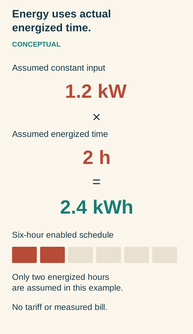
Energy uses actual energized time.
Illustrative arithmetic: an assumed constant 1.2 kW input for two actual energized hours gives 2.4 kWh. An enabled six-hour schedule does not establish six hours of input; this is not a bill or a saving claim.
Choose a part name to highlight its explanation below.
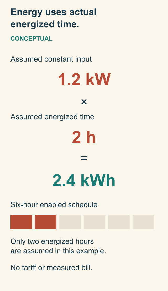
- Assumption 1
Constant electrical input while energized is assumed to be 1.2 kW. This is not the rating of an identified household system.
- Assumption 2
Actual energized time is assumed to total 2 hours. A six-hour enabled schedule is a different quantity.
- Arithmetic
Energy = 1.2 kW × 2 h = 2.4 kWh, using the defined power/time energy units.
- Limits
No tariff, currency, saving, annual-use forecast or measured operating result is represented. Actual controls and input can differ.
Energy uses actual energized time.
Illustrative arithmetic: an assumed constant 1.2 kW input for two actual energized hours gives 2.4 kWh. An enabled six-hour schedule does not establish six hours of input; this is not a bill or a saving claim.
- Assumption 1
- Constant electrical input while energized is assumed to be 1.2 kW. This is not the rating of an identified household system.
- Assumption 2
- Actual energized time is assumed to total 2 hours. A six-hour enabled schedule is a different quantity.
- Arithmetic
- Energy = 1.2 kW × 2 h = 2.4 kWh, using the defined power/time energy units.
- Limits
- No tariff, currency, saving, annual-use forecast or measured operating result is represented. Actual controls and input can differ.
Read all the diagram text
- Energy uses actual energized time.
- CONCEPTUAL
- Assumed constant input
- 1.2 kW
- ×
- Assumed energized time
- 2 h
- =
- 2.4 kWh
- Six-hour enabled schedule
- Only two energized hours are assumed in this example.
- No tariff or measured bill.
What should you know before calling the job finished?
You should be able to point to the actual heater format in the pictures and explain its route to the room. Is cable embedded above the base, is a dry heater below a suitable floating finish, or does an identified mat work from the joist space? Then ask what the installed sensor observes and how the control is intended to use it.
Keep one concise handover: actual product identities and manuals, the relevant floor construction and layout, installation or service records, ordinary operation and fault response. The useful question is not whether a folder is full. It is whether another provider can understand what is installed and what was changed.
For a new installation or a changed use, ask which heating goal was assessed and how the completed work will be explained. For a repair, ask what was found, what work was done and whether the original concern needs follow-up. These are ordinary questions a household can ask without becoming an electrical installer.
Canadian requirements and authorized trade roles depend on the location and actual work. The Ontario Electrical Safety Authority’s homeowner guidance is useful about involving a Licensed Electrical Contractor and reviewing the manufacturer’s requirements; it is not a licence rule for every province. Confirm the applicable local process with the qualified provider and authority.
The named manuals also have different editions and market scopes. They teach the physical differences here; they do not certify your hidden floor, prove a current listing for an unverified model or approve a product substitution. Keep the actual identities, current instructions and professional explanation tied to the home you are buying, renovating or living in.
Keep learning about the connected parts
Canadian context and authorities · Visual atlas · Learning labs
Know the parts.
Know what the words mean.
- Floor sensor
- A temperature-sensing component at an identified location in the floor assembly.
- Thermal response
- How an assembly’s temperature changes over time under stated heat input and surrounding conditions.
- Thermal break
- A layer intended to limit heat transfer at a particular part of an assembly; not automatically a complete insulation strategy.
- Insulation resistance
- A professional electrical assessment of unwanted leakage paths under its specified method.
- Resistance heater
- A manufactured element that converts electrical energy into heat; its form and permitted installation are product-specific.
- Carrier mesh
- The open supporting material that holds the heating cable in the illustrated mat; not itself a metal heating element.
- Uncoupling membrane
- A specified assembly component intended to manage movement between substrate and finish; a separate retained cable makes heat in the illustrated heated example.
- Floating floor
- A finish installed as its identified floating-floor system rather than mechanically fastened through a concealed heater.
- Busbar
- A conducting part that distributes electrical current to the heating portions of the illustrated film product.
- Heated area
- The actual area assigned heating in the design, which may be smaller than the room footprint.
- Floor warming
- An intended comfort goal for the floor surface, distinct from an assessed whole-room heating requirement.
Questions to bring
to the conversation.
- Which physical heater format and exact products are installed?
- What is the actual supporting floor, finish and intended heating goal?
- Where and what does the sensor measure in this system?
- What changed in ordinary use, the covering, furnishings or nearby work?
- Does the proposed work address the heater, control, floor assembly—or several of them?
Separate a showing observation, an existing record and a new professional assessment. Unknown means a question remains; it does not automatically mean a defect.
Use the evidence planner ↗Go to the source.
Original HomeAI explanation informed by these public references. Sources support the underlying guidance; they have not reviewed or endorsed HomeAI. Diagrams are conceptual, and calculator outputs depend on your inputs.
Canadian home-heating education, with product-specific examples qualified separately. Primary readings, editions, geography and reading limits are recorded with each reference. Illustrations explain recognizable parts and mechanisms; actual design, condition and repair decisions need the appropriate qualified professional.
Publication & source review
First published .
Sources reviewed .
- Schluter Systems · DITRA-HEAT Installation Handbook 10/2025
- Schluter Canada · DITRA-HEAT-E-R thermostat
- Natural Resources Canada · Electric heaters
- US Department of Energy Building Science Education: Heat Flow
- Schluter Canada: DITRA-HEAT-E-R thermostat
- NUHEAT · Cable Installation Guide, 2504 / April 2025
- Warmup · StickyMat instructions, v1.0 January 2015
- Schluter Systems · DITRA-HEAT Installation Handbook, 10/2025
- Warmup · Foil Installation Manual, V4.0 2013
- SunTouch · UnderFloor Mat Series U10 Installation Manual, 2022
- MP Global Products · QuietWarmth Float Installation Instructions
- Natural Resources Canada · Electric heaters
- Ontario Electrical Safety Authority · Hide Without the Seek / Hidden Conveniences
- US Department of Energy Building Science Education · Heat Flow
- Uponor · Residential Radiant and Hydronics Installation Handbook, 7th edition December 2023
Have a question about your home?
Start with the symptom, timing and what you have observed.
Ask HomeAI